7. Supported Network File Formats
Cytoscape can read network/pathway files written in the following formats:
Simple interaction file (SIF or .sif format)
Graph Markup Language (GML or .gml format)
XGMML (extensible graph markup and modelling language).
SBML
BioPAX
GraphML
Delimited text
Excel Workbook (.xls, .xlsx)
The SIF format specifies nodes and interactions only, while other formats store additional information about network layout and allow network data exchange with a variety of other network programs and data sources. Typically, SIF files are used to import interactions when building a network for the first time, since they are easy to create in a text editor or spreadsheet. Once the interactions have been loaded and network layout has been performed, the network may be saved to GML or XGMML format for interaction with other systems. All file types listed (except Excel) are text files and you can edit and view them in a regular text editor.
7.1. SIF Format
The simple interaction format is convenient for building a graph from a list of interactions. It also makes it easy to combine different interaction sets into a larger network, or add new interactions to an existing data set. The main disadvantage is that this format does not include any layout information, forcing Cytoscape to re-compute a new layout of the network each time it is loaded.
Lines in the SIF file specify a source node, a relationship type (or edge type), and one or more target nodes:
nodeA <relationship type> nodeB
nodeC <relationship type> nodeA
nodeD <relationship type> nodeE nodeF nodeB
nodeG
...
nodeY <relationship type> nodeZ
A more specific example is:
node1 typeA node2
node2 typeB node3 node4 node5
node0
The first line identifies two nodes, called node1 and node2, and a single relationship between node1 and node2 of type typeA. The second line specifies three new nodes, node3, node4, and node5; here “node2” refers to the same node as in the first line. The second line also specifies three relationships, all of type typeB and with node2 as the source, with node3, node4, and node5 as the targets. This second form is simply shorthand for specifying multiple relationships of the same type with the same source node. The third line indicates how to specify a node that has no relationships with other nodes. This form is not needed for nodes that do have relationships, since the specification of the relationship implicitly identifies the nodes as well.
Duplicate entries are ignored. Multiple edges between the same nodes must have different edge types. For example, the following specifies two edges between the same pair of nodes, one of type xx and one of type yy:
node1 xx node2
node1 xx node2
node1 yy node2
Edges connecting a node to itself (self-edges) are also allowed:
node1 xx node1
Every node and edge in Cytoscape has a name column. For a network
defined in SIF format, node names should be unique, as identically named
nodes will be treated as identical nodes. The name of each node will be
the name in this file by default (unless another string is mapped to
display on the node using styles). This is discussed in the section on
Styles.
The name of each edge will be formed from the name of the source and
target nodes plus the interaction type: for example,
sourceName (edgeType) targetName.
The tag “edgeType” can be any string. Whole words or concatenated words may be used to define types of relationships, e.g. geneFusion, cogInference, pullsDown, activates, degrades, inactivates, inhibits, phosphorylates, upRegulates, etc.
Some common interaction types used in the Systems Biology community are as follows:
  pp .................. protein - protein interaction
  pd .................. protein -> DNA
  (e.g. transcription factor binding upstream of a regulating gene.)
Some less common interaction types used are:
  pr .................. protein -> reaction
  rc .................. reaction -> compound
  cr .................. compound -> reaction
  gl .................. genetic lethal relationship
  pm .................. protein-metabolite interaction
  mp .................. metabolite-protein interaction
Delimiters
Whitespace (space or tab) is used to delimit the names in the simple interaction file format. However, in some cases spaces are desired in a node name or edge type. The standard is that, if the file contains any tab characters, then tabs are used to delimit the fields and spaces are considered part of the name. If the file contains no tabs, then any spaces are delimiters that separate names (and names cannot contain spaces).
If your network unexpectedly contains no edges and node names that look like edge names, it probably means your file contains a stray tab that’s fooling the parser. On the other hand, if your network has nodes whose names are half of a full name, then you probably meant to use tabs to separate node names with spaces.
Networks in simple interactions format are often stored in files with a
.sif extension, and Cytoscape recognizes this extension when browsing
a directory for files of this type.
7.2. GML Format
In contrast to SIF, GML is a rich graph format language supported by many other network visualization packages. The GML file format specification is available at:
http://graphviewer.nl/misc/gmllanguage/gml-technical-report.pdf
It is generally not necessary to modify the content of a GML file
directly. Once a network is built in SIF format and then laid out, the
layout is preserved by saving to and loading from GML. Properties
specified in a GML file will result in a new style named
Filename.style when that GML file is loaded.
7.3. XGMML Format
XGMML is the XML evolution of GML and is based on the GML definition. In addition to network data, XGMML contains node/edge/network column data. More information on Wikipedia:
https://en.wikipedia.org/wiki/XGMML
XGMML is now preferred to GML because it offers the flexibility associated with all XML document types. If you’re unsure about which to use, choose XGMML.
There is a java system property “cytoscape.xgmml.repair.bare.ampersands” that can be set to “true” if you have experience trouble reading older files.
This should only be used when an XGMML file or session cannot be read due improperly encoded ampersands, as it slows down the reading process, but this is still preferable to attempting to fix such files using manual editing.
7.4. SBML (Systems Biology Markup Language) Format
The Systems Biology Markup Language (SBML) is an XML format to describe biochemical networks. SBML file format specification is available at:
7.5. BioPAX (Biological PAthways eXchange) Format
BioPAX is an OWL (Web Ontology Language) document designed to exchange biological pathways data. The complete set of documents for this format is available at:
7.6. GraphML
GraphML is a comprehensive and easy-to-use file format for graphs. It is based on XML. The complete set of documents for this format is available at:
7.7. Delimited Text Table and Excel Workbook
Cytoscape has native support for Microsoft Excel files (.xls, .xlsx) and delimited text files. The tables in these files can have network data and edge columns. Users can specify columns containg source nodes, target nodes, interaction types, and edge columns during file import. Some of the other network analysis tools, such as igraph (https://igraph.org/), has feature to export graph as simple text files. Cytoscape can read these text files and build networks from them. For more detail, please read the Import Free-Format Tables section of the Creating Networks section.
7.8. Cytoscape.js JSON
From Cytoscape 3.1.0 on, Cytoscape supports Cytoscape.js JSON files. You can use this feature to export your network visualizations to web browsers. Cytoscape.js has two ways to represent network data, and currently both reader and writer support only the array style graph notation. For example, this network in Cytoscape:
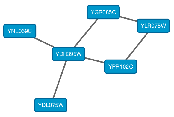
will be exported to this JSON:
{
  "elements" : {
    "nodes" : [ {
      "data" : {
        "id" : "723",
        "selected" : false,
        "annotation_Taxon" : "Saccharomyces cerevisiae",
        "alias" : [ "RPL31A", "RPL34", "S000002233", "ribosomal protein L31A (L34A) (YL28)" ],
        "shared_name" : "YDL075W",
        "SUID" : 723,
        "degree_layout" : 1,
        "name" : "YDL075W"
      },
      "position" : {
        "x" : 693.0518315633137,
        "y" : -49.47506554921466
      },
      "selected" : false
    }, {
      "data" : {
        "id" : "726",
        "selected" : false,
        "annotation_Taxon" : "Saccharomyces cerevisiae",
        "alias" : [ "RP23", "RPL16B", "S000005013", "ribosomal protein L16B (L21B) (rp23) (YL15)" ],
        "shared_name" : "YNL069C",
        "SUID" : 726,
        "degree_layout" : 1,
        "name" : "YNL069C"
      },
      "position" : {
        "x" : 627.3147710164387,
        "y" : -205.99251969655353
      },
      "selected" : false
    }, {
      "data" : {
        "id" : "658",
        "selected" : false,
        "annotation_Taxon" : "Saccharomyces cerevisiae",
        "alias" : [ "RPL11B", "S000003317", "ribosomal protein L11B (L16B) (rp39B) (YL22)" ],
        "shared_name" : "YGR085C",
        "SUID" : 658,
        "degree_layout" : 2,
        "name" : "YGR085C"
      },
      "position" : {
        "x" : 804.3092778523762,
        "y" : -245.6235926946004
      },
      "selected" : false
    }, {
      "data" : {
        "id" : "660",
        "selected" : false,
        "annotation_Taxon" : "Saccharomyces cerevisiae",
        "alias" : [ "KAP108", "S000002803", "SXM1" ],
        "shared_name" : "YDR395W",
        "SUID" : 660,
        "degree_layout" : 8,
        "name" : "YDR395W"
      },
      "position" : {
        "x" : 730.8733342488606,
        "y" : -157.50702317555744
      },
      "selected" : false
    }, {
      "data" : {
        "id" : "579",
        "selected" : false,
        "annotation_Taxon" : "Saccharomyces cerevisiae",
        "alias" : [ "RPL11A", "S000006306", "ribosomal protein L11A (L16A) (rp39A) (YL22)" ],
        "shared_name" : "YPR102C",
        "SUID" : 579,
        "degree_layout" : 2,
        "name" : "YPR102C"
      },
      "position" : {
        "x" : 841.1395696004231,
        "y" : -130.77909119923908
      },
      "selected" : false
    }, {
      "data" : {
        "id" : "578",
        "selected" : false,
        "annotation_Taxon" : "Saccharomyces cerevisiae",
        "alias" : [ "GRC5", "QSR1", "RPL10", "S000004065", "ribosomal protein L10" ],
        "shared_name" : "YLR075W",
        "SUID" : 578,
        "degree_layout" : 2,
        "name" : "YLR075W"
      },
      "position" : {
        "x" : 910.3755162556965,
        "y" : -217.0562556584676
      },
      "selected" : false
    } ],
    "edges" : [ {
      "data" : {
        "id" : "659",
        "source" : "658",
        "target" : "578",
        "selected" : false,
        "interaction" : "pp",
        "shared_interaction" : "pp",
        "shared_name" : "YGR085C (pp) YLR075W",
        "SUID" : 659,
        "name" : "YGR085C (pp) YLR075W"
      },
      "selected" : false
    }, {
      "data" : {
        "id" : "661",
        "source" : "658",
        "target" : "660",
        "selected" : false,
        "interaction" : "pp",
        "shared_interaction" : "pp",
        "shared_name" : "YGR085C (pp) YDR395W",
        "SUID" : 661,
        "name" : "YGR085C (pp) YDR395W"
      },
      "selected" : false
    }, {
      "data" : {
        "id" : "724",
        "source" : "660",
        "target" : "723",
        "selected" : false,
        "interaction" : "pp",
        "shared_interaction" : "pp",
        "shared_name" : "YDR395W (pp) YDL075W",
        "SUID" : 724,
        "name" : "YDR395W (pp) YDL075W"
      },
      "selected" : false
    }, {
      "data" : {
        "id" : "733",
        "source" : "660",
        "target" : "579",
        "selected" : false,
        "interaction" : "pp",
        "shared_interaction" : "pp",
        "shared_name" : "YDR395W (pp) YPR102C",
        "SUID" : 733,
        "name" : "YDR395W (pp) YPR102C"
      },
      "selected" : false
    }, {
      "data" : {
        "id" : "727",
        "source" : "660",
        "target" : "726",
        "selected" : false,
        "interaction" : "pp",
        "shared_interaction" : "pp",
        "shared_name" : "YDR395W (pp) YNL069C",
        "SUID" : 727,
        "name" : "YDR395W (pp) YNL069C"
      },
      "selected" : false
    }, {
      "data" : {
        "id" : "580",
        "source" : "578",
        "target" : "579",
        "selected" : false,
        "interaction" : "pp",
        "shared_interaction" : "pp",
        "shared_name" : "YLR075W (pp) YPR102C",
        "SUID" : 580,
        "name" : "YLR075W (pp) YPR102C"
      },
      "selected" : false
    } ]
  }
}
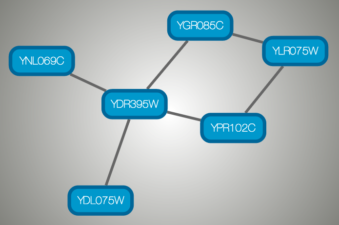
And this is a sample visualization in Cytoscape.js:
Important Note
Export network and table to Cytoscape.js feature in Cytoscape creates a JSON file WITHOUT style. This means that you need to export the style in a separate JSON file if you apply style to your network. Please read the Style section for more details.
7.9. Cytoscape CX
CX is a JSON-based transfer format that enables diverse Cytoscape Cyberinfrastructure (CI) services to exchange networks while preserving all network-related information. It is designed for flexibility, modularity, and extensibility, and as a message payload in common CI REST protocols. It enables applications to standardize on core aspects of networks, coordinate on more specific or unique standards, and to ignore or omit irrelevant aspects. It is not intended as an optimized format for storage or for specific functionality in applications.
CX is an Aspect-Oriented Network Interchange Format, where the base information is a list of nodes. Independent data structures (called aspects) organize and elaborate on nodes and each other. The core of CX defines five aspects, though a more comprehensive CX document describes many more aspects.
| Aspect | Purpose |
|---|---|
| networkAttributes | element specify name-value pairs describing the network |
| nodes | elements specify the identifiers for nodes in a network, optionally specifying a node name |
| edges | elements specify edges that connect nodes, optionally specifying a interaction |
| nodeAttributes | elements specify name-value pairs describing nodes |
| edgeAttributes | elements specify name-value pairs describing edges |
The nodes aspect contains only the identifiers of the network’s nodes, The edges aspect contains identifiers for each edge along with the identifiers of the nodes the edge connects. The networkAttributes aspect contains name-value pairs describing the network. The nodeAttributes and “edgeAttributes” aspects contain name-value pairs attached to specifically identified nodes and edges.
Critically, applications are free to add and maintain their own aspects without coordinating or negotiating with disinterested applications.
As an illustration using the picture below, a three node network can be described as a list of nodes (nodes aspect) and edges that link them (edges aspect). If the network has been laid out, a separate aspect (cartesianLayout aspect) can describe the position of each node. More concretely, a CX encoding would have three nodes in the nodes aspect, each with unique IDs. The edges aspect references each node by ID, with each edge having its own ID. Finally, the cartesianLayout aspect ties coordinates to nodes by ID. In fact, a network may have many aspects, describing node and edge attributes, subnetworks, visual properties, groups and so on.
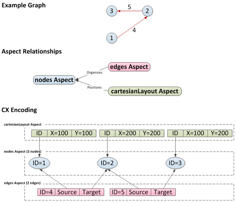
The actual JSON encoding for a CX stream is described in the CX document. It would appear something like this:
{
  "nodes": [{"@id": 1}, {"@id": 2}, {"@id": 3}],
  "edges": [{"s": 1, "@id": 4, "t": 2},
            {"s": 2, "@id": 5, "t": 3}],
  "cartesianLayout": [{"x": 100, "node": 1, "y": 100},
                      {"x": 200, "node": 2, "y": 200},
                      {"x": 100, "node": 3, "y": 200}]
}